#Limit Switch Microswitch
Explore tagged Tumblr posts
Visit Tumblr Blog
Explore Tumblr blogs with no restrictions, modern design and the best experience.
Last Seen Tumblr Blogs


Fun Fact
Tumblr was acquired by Yahoo for $1.1B in 2013.
Text
Essen offer microswitches are precision-engineered miniature snap-action switches designed for reliability and versatility in various applications. They feature a spring-loaded mechanism that responds swiftly to minimal force, ensuring precise control over electrical circuits or detection of physical movements.
1 note
·
View note
Text
Arkodd Padbox Review: a fightpad for the arcade afficionado

by Amr (@siegarettes)
Sporting a clicky dpad and an enclosure large enough to accommodate 24mm arcade buttons, the Arkodd Padbox is a controller/fightstick hybrid set to fill the niche left by a lack of good 6 button fightpads.
The dpad is equipped with Omron mechanical switches, similar to the ones used in arcade sticks, and a left shoulder button and additional thumb button complement the standard 8 button layout, allowing access to extra functions and alternative button placements.

The Padbox comes as fully assembled units or DIY kits that include the case, dpad, wiring and function buttons. For this review I opted for the DIY kit, since I wanted to see what the build process was like, and customize the build with parts I had on hand.
Full disclosure: I was sent this kit to review, but I wasn’t given any instructions or limitations on what I could say.
With that out of the way, what immediately impressed me was how easy the build process was. The Padbox comes apart with only a few screws, and the dpad, shoulder button and aux buttons are already pre-installed. The wiring harnesses provided are sized appropriately for the available space, and headers for the dpad and shoulder buttons, alongside pre-made dupont connectors made wiring them to the screw terminals simple.

If there’s one thing to note it’s that the Padbox uses a direct USB connection for its USB C jack, rather than the Neutrik Type-D passthrough ports that many custom fightstick builds use. The connector is designed with Brook Fighting Boards in mind, which have pre-populated headers for USB, but I opted to use a RP2040 Advanced Breakout Board I had on hand to get access to the advanced features of GP2040ce. If you do goes this way, make sure you get the latest version of the board with the screw terminals for the extra functions, as those have pre-populated USB headers, otherwise you’ll have to solder on your own like I did.
You’ll also need to plug into the 5v VCC terminal for the power indicator LED, though if you are somehow doing an even more niche build of a niche product, and using a Brook Wireless board for it, you’ll need to connect to the player indicator LEDs instead, since the 5v terminal won’t output when running on battery.
Aside from these incredibly niche considerations, the overall build process is fast and painless. I built it all on a weeknight after work, and I even had time to stickerbomb it and test out a few games with it. I’ve had a harder time modding some fully built fightsticks.
Now the most important question: how’s the dpad. In short: they nailed it. No matter what style of game I played it was easy to get my inputs out, with no accidental inputs. After using so many controllers and handhelds, I can tell you this is a hell of an accomplishment. Even mechanical dpads aren’t a silver bullet to this problem, as I’ve seen so many of them with the same kind of satisfying feedback that are miserable in practice. So I’m happy to report that this dpad is not one of them.
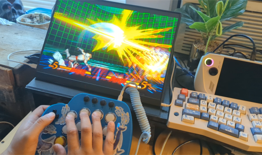
One of the first games I tried the Padbox with was Ultimate Marvel vs Capcom 3’s trial mode, my go to for testing new fighting game controllers. Here it performed better than basically any first party controller dpad, with the combo of the microswitch dpad and larger arcade buttons making it easy to get in rhythm. The same happened in Street Fighter 6, where the extra buttons allowed me to access Drive Functions easier than the standard 8 button layout, and the shoulder button provided comfortable access to the assist function for characters I play with Modern Controls.
For anyone who plays primarily on pad, I could definitely see this as an upgrade to a regular gamepad or fightpad, especially for those who play claw grip and wouldn’t miss the extra shoulder buttons. With the swappable buttons, an all mechanical controller is even possible, given the growing options for buttons with keyboard style switches.
Personally, the Padbox won’t likely stay in rotation for playing fighting games, despite how much I like it. The Padbox can’t solve the fundamental problem I have with playing fighting games on pad: it’s too cramped. As someone particularly sensitive to this issue, I find that putting all the strain on my thumb wears me down faster when performing complex inputs, and the Padbox made it clear that for me, no pad can compete with the comfort of leverless for competitive games.
But who says you can only use a fighting game controller for fighting games?
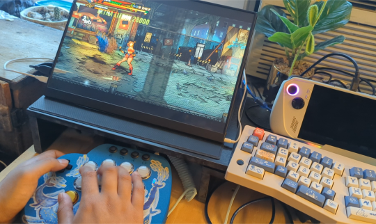
Arcade buttons are plenty of fun across multiple genres, and with its hybrid design, the Padbox enables a variety of approaches that both traditional fightsticks and pads can’t provide. I tested it with beat-em-ups like Streets of Rage 4 and Shredder’s Revenge, where the arcade layout made performing combos a joy.
Retro consoles and throwback games are another good candidate, with the tactile feedback a the Padbox’s dpad a definite upgrade to a lot of the membrane dpads and buttons of original controllers, with the bonus of arcade buttons being a lot more fun to mash in the many games that demanded it.
Action games that make limited use of the right stick for camera control are totally playable with the Padbox, and with the use of GP2040ce, you can even use the extra buttons to create modifiers that give you on the fly access to the dpad or right stick for item hotkeys or camera control.
I even managed to make a playable control scheme for Smash Bros Ultimate, complete with c-stick buttons for tilt and aerial attacks.
The Padbox might not be my personal choice for serious fighting game competition, but it’ll definitely stay in rotation as one of my alternative controllers for casual fighting, and playing plenty of other genres.
If there's any additions I'd like to see, it's the addition of additional shoulder and thumb buttons. These would not only give access to an extra shortcut button in fighting games, but enable layouts with extra functions or modifiers, such as tilt modifiers or dual directional input in the style of the Hitbox Crossup.
The Padbox is also a bit lightweight. It comes in a little heavier than a standard controller, but it's spread out across a larger surface area, and alongside the slickness of the 3D printed material, it threatens to slip during those literally sweaty matches. An optional metal bottom plate or a removable weight for the grip might help give it heft for longer play sessions and lap play.
My favorite part of the Padbox has to be how many possibilities it leaves open. With its form factor, it's easy to start thinking of new ways to mod the Padbox and make it your own. It brings the DIY spirit of arcade sticks to a pad, and I've already seen wild molds replacing the dpad with a split dpad, or building entire new bases for it and adding more buttons.
If you're a controller enthusiast looking for a good fightpad, or just something with a real good dpad, consider giving the Padbox a look.
2 notes
·
View notes
Text
Crouzet Products at Aeliya Marine: Powering the Future of Industrial Automation
In the constantly changing age of industrial automation, having trusted, precision-built components is key. Whether you’re creating new-generation technologies or supporting vital marine and industrial applications, the reliability of your automation components directly reflects your performance, efficiency, and bottom line.
Among the automation giants, Crouzet is a leader in innovation and excellence. Renowned for their world-class expertise in manufacturing relays, switches, controllers, and motion solutions, Crouzet has established a strong reputation through decades of uncompromising focus on quality.
At Aeliya Marine Tech, we are pleased to introduce you to an in-depth range of Crouzet products to fulfill your various industrial requirements. Be you an engineer, procurement manager, maintenance expert, or an automation enthusiast, Aeliya Marine is your go-to partner to source world-class Crouzet solutions with utmost confidence.
In this detailed guide, we’ll explore Crouzet’s rich legacy, the key categories of products they offer, the applications they power, and why Aeliya Marine is your go-to destination for purchasing authentic Crouzet automation equipment.
A Legacy of Innovation : Who is Crouzet ?
Established in France in 1921, Crouzet has grown its heritage through precision, dependability, and customer-driven innovation. It specializes in designing and producing automation control components for critical applications in diversified industries like aerospace, automotive, medical, rail, and industrial automation.
From the original electromechanical timers to today’s intelligent smart automation modules, Crouzet has remained dedicated to providing smarter, safer, and more efficient solutions. Its components are designed to withstand the toughest environments and provide high performance in the most demanding applications.
Nowadays, Crouzet is present globally, backed up by research and development labs, production plants, and a robust distribution partner network such as Aeliya Marine that makes its solutions readily available to customers worldwide.
Crouzet Product Categories Available at Aeliya Marine
At Aeliya Marine, you can find an extensive variety of Crouzet products designed to fulfill the needs of contemporary industrial control and automation solutions. Below is an overview of the main categories:
1. Timers and Counters Crouzet is world-renowned for its high-performance counters and timers. Applications vary from basic time-delay relays to intricate sequencing operations in production lines. Their products are characterized by high precision, durability, and flexibility with digital and analog models available.
Highlights:
Multi-function timers
Digital and analog counters
DIN rail and panel mount options
Long operational lifespan
2. Relays and Solid-State Relays
Crouzet relays are relied upon for switching applications between various voltages and currents, providing the highest reliability in control systems.
Types are:
Electromechanical relays
Solid-state relays (SSR)
Monitoring and measuring relays
Applications:
Control panels
HVAC systems
Automation systems
Machine tools
3. Switches and Sensors
For accurate detection and actuation applications, Crouzet provides a variety of switches and position sensors. Their limit switches, microswitches, and proximity sensors provide the reliability required in mission-critical systems.
Typical Uses:
Door interlocks
Conveyor belt systems
Safety monitoring
Industrial robotics
4. Motion Control Solutions
Crouzet’s electronic drives, brushless DC motors, and geared motors provide a trusted motion control for mobility and automation applications.
Product Range:
DC Brushless Motors
Stepper Motors
Gear Motors
Integrated Drives
Their efficiency, long lifetime, and small size make them ideal for medical equipment, mobile robots, and automated machinery.
5. Controllers and Programmable Logic Devices
In addition, Crouzet supplies programmable controllers, used extensively to automate small machines, process controls, and lighting systems. Easy yet robust, their Millenium 3 Logic Controllers are especially favored by OEMs and engineers seeking adaptable automation.
Important Features:
Easy to program
Expansibility
Multi-protocol communications
Why Crouzet ?
In today’s aggressive industrial and marine automation markets, Crouzet has a number of important differentiators:
Tried-and-True Reliability : Designed to withstand harsh environments, including marine applications.
Innovative Design : Crouzet continuously innovates, embedding new technologies to optimize functionality and usability.
Global Standards : Their products meet stringent international standards (such as IEC, UL, and CE) ensuring you’re investing in quality.
Versatility : Suitable for diverse applications from small devices to complex industrial machinery.
Industries Powered by Crouzet
The versatility and robustness of Crouzet products mean they are trusted across multiple industries:
Marine and Shipbuilding : Automation, navigation systems, motor controls, safety mechanisms.
Manufacturing : Robotics, conveyors, production lines, and quality control automation.
Aerospace and Defense : Aircraft systems, defense equipment, communication controls.
Medical Devices : Surgical devices, imaging systems, hospital automation.
Railway and Transportation : Train doors, signaling systems, and safety monitoring.
Energy and Environment : Wind turbines, solar trackers, and water treatment plants.
Why Buy Crouzet Products from Aeliya Marine?
Aeliya Marine Tech is not only another supplier — we are a specialized industrial and marine automation partner that customers trust globally.
Here’s why clients select us consistently :
Broad Selection : From old models to the newest Crouzet innovations — we carry it all.
Original Products : 100% original parts directly sourced from reputable manufacturers and distributors.
Competitive Prices : We think quality automation should be affordable.
Quick Global Shipping : No matter where you are in India, the Middle East, Europe, or the Americas, we ship quickly.
Expert Advice : Our technical experts help you choose the appropriate components for your projects.
Customer Satisfaction : Customized service, hassle-free buying, and post-sales support.
At Aeliya Marine, we know the vital role of dependable automation in industrial and marine processes. That’s why we don’t just sell products — we develop long-term partnerships with our customers, making their systems operate reliably and efficiently.
Featured Crouzet Products You Can Discover
Crouzet Timer Relay Series : Accurate time management solutions for automation cycles.
Crouzet 841 Series Relays : Compact, heavy-duty relays for switching.
Crouzet Limit Switches : Accurate detection in manufacturing systems.
Crouzet Millenium 3 Logic Controllers : Programmable, compact, flexible PLCs.
Crouzet DC Motors and Drives : Robust motors for industrial and robotic movement.
And many more!
How to Order Crouzet Products from Aeliya Marine
Ordering from Aeliya Marine is easy and hassle-free :
Browse our Crouzet collection here.
Select your required product(s).
Contact our sales team for a quotation if needed.
Checkout securely through our website.
Sit back and relax we’ll deliver your product safely and promptly.
For bulk orders, special discounts, or technical inquiries, you can also get in touch with us directly. We’re always ready to assist you!
Industrial and marine automation requires components engineered to perfection components that will be relied upon to perform, even in the most demanding conditions. Crouzet has consistently demonstrated that precision, quality, and innovation are the core of their solutions. And with Aeliya Marine Tech, we’re pleased to be able to bring these first-class solutions to you personally.
Settle for nothing less when it comes to your automation requirements. Discover the entire lineup of Crouzet products today at Aeliya Marine and fuel your success!
Shop Now Crouzet at Aeliya Marine Tech
#industrial equipment#automation#industrial spare parts#industrialautomation#industrial and marine automation#industrial automation#marine automation#pcb#amplifier#meter#Crouzet
0 notes
Text
Metal Button Switches in Human-Machine Interaction Design of New Energy Vehicle Cockpits

With the rapid development of new energy vehicle technology, cockpit design is continuously evolving to enhance the driving experience, safety, and convenience. Among these developments, metal button switches, as a traditional form of physical control, continue to play a crucial role in the cockpits of new energy vehicles. Although touchscreens, knobs, and other control methods are increasingly being adopted, metal button switches remain irreplaceable in the design of new energy vehicle cockpits due to their intuitiveness, reliability, and premium feel.
This article will explore the application of metal button switches in the cockpits of new energy vehicles, examining their synergistic interaction with touchscreens and knobs, the relationship between tactile feedback and driving safety, and analyzing the importance of metal button switches in modern new energy vehicle design through practical case studies.
1. Synergistic Interaction between Metal Button Switches, Touchscreens, and Knobs
In the cockpits of modern new energy vehicles, touchscreens, knobs, and physical buttons together form a multimodal Human-Machine Interface (HMI) system.
1.1 Advantages and Limitations of Touchscreens
Touchscreens offer a flexible interaction method with dynamically adjustable user interfaces (UI), enabling a richer set of functions while reducing the number of physical buttons, enhancing cockpit simplicity. However, there are several limitations when it comes to driving:
Risk of accidental touches: While driving, touchscreens lack physical feedback, which causes drivers to divert their attention and increases the risk of making errors.
Difficulty in operation with wet hands or gloves: In humid environments or when wearing gloves in winter, capacitive touchscreens may be difficult to operate.
Response delay: Some touchscreens may have slow response times or system lag, which negatively affects the driving experience.
1.2 Characteristics of Knobs
Knobs are typically used for volume control, switching driving modes, etc. Compared to touchscreens, knobs offer tactile feedback, making operations more intuitive. However, knobs generally require other input methods to be used in conjunction with them, making them less effective for complex operations on their own.
1.3 Role of Metal Button Switches
Metal button switches bridge the gaps left by touchscreens and knobs, providing efficient, intuitive, and reliable interaction.
Key function control: Functions such as start/stop buttons, emergency shutdown, and driving mode selection require intuitive and immediate feedback, for which metal buttons are the best choice.
Improving safety: While driving, the tactile feel of metal buttons allows the driver to recognize their shape and position, minimizing visual distraction.
Enhancing the driving experience: The mechanical feedback provided by metal buttons allows the driver to immediately confirm that the input has been successfully executed, improving operational reliability.
2. Tactile Feedback and Driving Safety
2.1 Tactile Feedback Mechanism of Buttons
Tactile feedback is one of the key advantages of metal button switches, which can be enhanced through different designs to improve the driving experience, including:
Button travel: Short travel (0.3~1.0mm) buttons provide clear tactile feedback, while long-travel buttons are suitable for scenarios requiring greater force.
Operating force: Typically in the range of 3N to 7N, appropriate pressure prevents accidental touches while offering a comfortable feel.
Feedback type: Mechanical, microswitch-based, or haptic vibration feedback can be selected based on the application scenario for optimal design.
2.2 Impact of Tactile Feedback on Driving Safety
Studies show that tactile feedback from physical buttons can significantly reduce driver distraction. For example, BMW's iDrive system combines a knob with a few physical buttons, while Tesla’s Model 3/Model Y has eliminated most physical buttons, relying entirely on the touchscreen. Some users have reported that the absence of traditional physical buttons reduces operational intuitiveness.
Metal button switches still play an important role in the human-machine interaction design of new energy vehicle cockpits. Despite the increased use of touchscreens and knobs, metal buttons remain the preferred choice for controlling key functions due to their intuitive operation, stable tactile feedback, and premium materials.
In the future, the HMI design of new energy vehicles is likely to evolve toward a combination of "physical buttons + touch interaction + voice control" to meet different user preferences. For new energy vehicle manufacturers, it will be crucial to retain the application of metal buttons while enhancing intelligence, optimizing user experience, and improving safety.
Metal buttons are not just relics of mechanical control but an indispensable part of modern automotive engineering. When applied correctly, they bring a better balance to the driving experience in new energy vehicles.
en.dghongju.com
0 notes
Text
Temperature Switch
The model 700 temperature Switch has been designed for control and monitoring applications. The stainless steel case option enables the temperature switch to perform in harsh operating conditions of the process industry. The switch point repeatability of ±0.5 or 1% enables reliable switching in critical operating conditions. Model 721, 723, 781, 771, 773 & 774 comes with capillary systems for remote sensing and Model 731, 733, 734 with rigid-stem thermal systems for limited space measurements enable to meet a variety of applications in oil, gas, power, steel and petrochemical industries.
Adjustable switch differential combinations are available to realize flexible on/off controls. This wide setting range is often needed for the on/off control mode of cyclic applications. The switch point can be specified on-site, with internal adjustment options. Depending on the application, the appropriate variant for the contact version and the electrical connection can be selected. For example, hermetically sealed microswitches are suitable for hazardous ambient conditions.
0 notes
Text
had a busy week so far and the two (or three, if I do the far future sad one) all require mucking about with textools for necessary props - one requires something that might work as some kind of photo plate, another needs a painting as a prop, and the third would require turning a minion into a bed with some extras. So I haven’t really gotten anywhere with that, or really done much in the game except a lot of idling really.
Instead, my brain’s been on a weird retro-bent about old electronic hardware, particularly focused on joysticks and the ways in which they can be customised or even entirely DIY:ed these days - more under the cut.
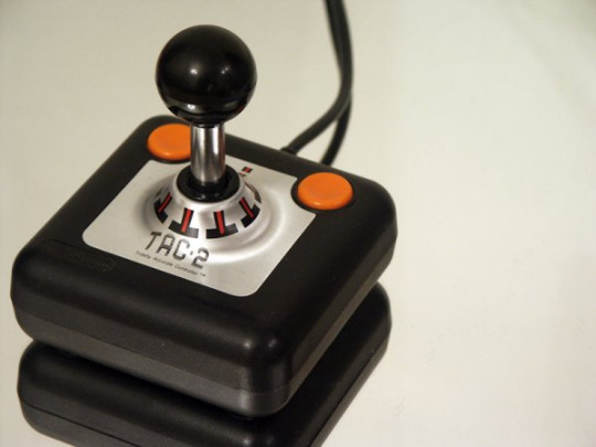
So early game joysticks were basically just D-pads with a long pole in the centre - electronically implemented as basically four buttons: up, down, left, right, with an additional fire button either on the stick or the base. In fact, the venerable TAC-2 joystick from 83 (depicted below) had no electronics or circuitry at all and worked entirely through metal contact surfaces.
In fact, the typical 4-way PoV hat switches mounted on the top of modern joysticks basically still work exactly like this, just with four regular 6x6 microswitches arranged in a plastic shell surrounding a pole - the following is the PoV hat assembly from a Mad Catz F.L.Y. 5 joystick from ‘09, for example:
So that’s basically just a D-pad, but with a vertical shaft instead of a flat cross or circle.
Now, while having your directional input limited across two all-or-nothing axes can serve perfectly well or even be outright preferable a lot of the time - a lot of fond old games platforms like the NES, the SNES, the Mega Drive, and the Commodore 64 all used that method pretty much exclusively - there’s definitely occasions when a more gradual directional input would serve far better.
Enter the analog joystick. Instead of four buttons arranged along the cardinal directions, these typically operate by means of having a pair of variable resistors, one for each direction, set up to either slide or rotate along with the motions of the stick, thereby providing that gradual input where each direction has more like an intensity value rather than end point triggers. Things like flight simulators are the most obvious use case for this, but this more or less how anything that provides bounded analog input works, from flight sticks to steering wheels to modern thumbsticks on your PS4 or Xbox One controllers.
In fact, if you look at the physical implementation of controller thumbsticks, most are basically just a pair of rotary potentiometers with a standard 6x6 microswitch added so you can also use it as a button press.
Of course, I say most, because variable resistors isn’t the only way of doing this. It’s a very simple, cheap, and common solution - in fact, the above image is meant to be for a pair of replacement thumbstick modules for PS4 controllers, and ones for the PS5, Xbox series including the Elite controllers, and the Switch Pro all use basically identical-looking modules just with slightly different potentiometers. So clearly this solution definitely works, and pretty well at that.
Though if you’ve ever experienced joystick (or thumbstick) drift, you might not necessarily agree with the “pretty well” part of that.
See the the way a potentiometer works is basically like this.

You have a length of resistive material, and a contact point that physically connects to it, and as you move the contact point along this material, the electrical resistance between it and the source terminals changes based on distance due to how far the signal has to travel through the resistive material. And by then measuring that resistance, you can fairly easily calculate what the potentiometer is set to. What this also means however, is that when you move the contact point around (ie: you use the joystick/thumbstick), there will inevitably be friction between the contact point and resistive material, and this friction will wear on these components, resulting in degrading performance and accuracy over time.
And this is inevitable - no component lasts forever. If you look up the specifications for a particular potentiometer or microswitch, there will typically be data for how much use they can be expected to stand before starting to become unreliable - these numbers are typically in their tenths of thousands at lowest and up into the several millions range at the other end. For some components there’s even separate life spans listed for the mechanical and electrical parts, as these degrade separately - as an example: if you press a button that isn’t connected to anything, that still presents mechanical wear on the moving parts within it, even if there’s no power connected.
Enter the Hall Effect sensor.
The Hall Effect is a particular way in which electrical current travelling through a conductor will be affected by magnetic fields - the particulars are, for the purposes of this post, unimportant - and also something I’d have to remember far more of what physics I learned back in the day than I actually do to actually understand. What does matter is that there exists components such as the above 49E which will output the same kind of signals as a regular potentiometer while moving within a magnetic field. And since this means the sensor doesn’t actually have to physically rub up against something else, there’s no friction involved and the only wear is electrical.
Their contactless nature and pretty high lifespan even for the cheaper ones has made them pretty much the dominant sensor type for the main joystick axes in high end flight sticks these days. And the fact that you can get them fairly cheaply combined with the gradual proliferation of 3d printing has led to a number of people doing DIY modifications to existing joysticks, or even making their own entirely using 3d printed parts and arduino boards.
This has now been a very long preamble to what is basically me pointing out that I recently got my hands on one of these:
The Quickshot Super Warrior.
Released in 94 sometime, it’s a PC joystick of the old gameport era, sporting X/Y directional axes, a throttle, four buttons, and an autofire toggle. For its time, it’s an extremely normal and straightforward PC joystick with very standard capabilities and no real special functions or features that you wouldn’t expect from any other typical joystick of its time.
It’s also the particular model of joystick that I spent hours upon hours playing games like TIE Fighter and Wing Commander and their like some 20-25 years ago, so there’s some serious nostalgia involved in putting my hands on one again after all these years.
Now this thing is old, and the one I got is definitely second hand as I bought it from a charitable organisation; even if through some miracle the potentiometers happened to be in tip top shape, I have no way of really telling because PCs stopped shipping with the old gameport a good decade or two ago after USB basically made the connector functionally obsolete. And sure, there’s gameport-to-USB converter devices you can buy, but for all my nostalgia for this thing... I remember having to deal with trim sliders to get it to maintain its centre being an absolute pain in the backside.
So! My plan is... I’m going to gut the original electronics from this thing and replace them with something more up to date, as well as see about adding some more buttons and features such as stick twist for rudder control and so forth! My original idea was to use the electronics from a Thrustmaster T.16000M, but there’s some awkward factors that makes that a more difficult proposition than I’d initially expected, so I may just end up going the arduino route and have this as an entirely custom thing.
I’m also thinking about dual-stick setups for a sort of stick-and-omnithrottle approach since I’ve never managed to get used to the throttles in more traditional HOTAS setups, but we’ll see.
And this has been a very long post that I’m not sure is particularly interesting to anyone, so good work if you’ve managed to stick with it this far I guess! xD
2 notes
·
View notes
Text
UNIONWELL MICRO SWITCH LIMIT SWITCH MANUFACTURER SUPPLIER FACTORY
MICRO SWITCH LIMIT SWITCH MANUFACTURER
The microswitch is a switch that is used in electronics, to interrupt or divert currents of small intensity: this is what a microswitch is . It is also called a micro switch because the contact distance of the switch is quite small. It is, in fact, a type of switch with a contact mechanism that is covered by a shell and has a control bar outside the switch itself. A minimum force is required to operate a microswitch.
The microswitch is a solution that has been designed to control the movement of a mechanical part and is used in appliances, electronic equipment, automatic machines and electric cars. The market offers different types of microswitches that can be easily adapted to different equipment and different needs. You will not have trouble finding the one that's right for you.
Microswitch: types
On the market you can find different types of microswitches:
Watertight microswitch
The watertight microswitch is located inside the gas water heater, different from the instant electric water heater , and is a kind of quick switch that is activated by pressure and is also called a sensitive switch . This microswitch consists of a small connecting shaft, a bracket, a microswitch body and a shift fork. How does it work? The external mechanical force exerts a force on the increase of the action through the transmission element which can be a wifi or traditional electrical socket , a button or a lever. The microswitch has a small contact distance, a short stroke, a small power and a quick ignition.
Slide microswitch
The slide switch is used to control the flow of current in a circuit and uses a mechanical slider to switch the current on and off. It is suitable for current flow control in small circuits, it is easy to see it used as a power switch in small battery powered electrical devices. It works similar to a push button switch, however it has a more noticeable shape to the touch, which allows the user to switch between the on and off states more easily .
12v microswitch
The 12v microswitch is useful for controlling the switching on or off of different types of circuits. It can be applied to cars, engines, water dispensers and many other equipment. Different models of this type of microswitches can be found on the market:
take it,
push-button,
with LED light,
in steel.
Surely you can easily buy the solution that suits you best.
1 note
·
View note
Text
Introduction to the instructions and skills of pressure relays

The pressure relay is a component in the hydraulic system that makes the electrical contacts act when the fluid pressure reaches a predetermined value. When the liquid pressure entering from the oil inlet at the lower end of the relay reaches the set pressure value, push the plunger to move up, the displacement is amplified by the lever and then pushes the micro switch to activate. By changing the compression of the spring, the active pressure of the relay can be adjusted.
Instructions
When first used for safety protection, set the pressure relay at one end of the clamping hydraulic cylinder. After the hydraulic pump is started, the workpiece is clamped first. At this time, the pressure of the right cavity of the clamping hydraulic cylinder rises. When the set value is set, the pressure relay acts and sends an electrical signal to energize, so the cutting hydraulic cylinder feeds and cuts. During processing, the normally open contacts of the pressure relay microswitch are always closed. If the workpiece is not clamped, the pressure relay is disconnected, so the power is cut off, and the cutting hydraulic cylinder stops feeding immediately, so as to avoid accidents caused by the workpiece being cut without being clamped.
In fact, when it is used to control the sequential actions of the actuators after the hydraulic pump is started, it is first powered on, and the left cavity of the hydraulic cylinder enters the oil to push the piston to the right. When the limiter (or dead block iron) is encountered, the system pressure rises, the transformer sudden pressure relay sends an electrical signal to energize, and the high-pressure oil enters the left chamber of the hydraulic cylinder to push the piston to the right. At this time, if the power is turned on, the piston of the hydraulic cylinder moves to the right quickly; if the power is off, the piston of the hydraulic cylinder moves to the right slowly, and its slow movement speed is adjusted by the throttle valve.
When it is used for unloading the hydraulic pump again, the pressure relief relay does not control the hydraulic pump to stop rotating but controls the two-position two-way solenoid valve to flow the pressure oil output by the hydraulic pump back to the oil tank to unload it.
Finally, when it is used for opening and closing the hydraulic pump, there are two hydraulic pumps, a high-pressure small-flow pump, and a low-pressure large-flow pump. When the piston descends rapidly, the two pumps output pressure oil at the same time. When the piston rod of the hydraulic cylinder presses against the workpiece, the rapid pressure relay acts under the action of the pressure oil, triggers the micro switch, disconnects the normally closed contact, and stops the hydraulic pump. Slow down the hydraulic cylinder during machining while reducing power consumption.
Skills
The pressure relay can sense the pressure of the system and send a switch signal. When the pressure is reached, the normally open contact closes and the normally closed contact opens. We can use it programmatically. But in actual use, we will encounter some problems.
First of all, there is a problem with the quality of the selected product, which is mainly reflected in the following aspects
1. The action is slow, and there is no signal output when the pressure is reached because there is no test when leaving the factory.
2. The message is sent before the pressure is conveyed because the micro switch in the pressure relay is not installed properly.
3. The short life of the pressure relay is because the manufacturer used inferior micro switches.
4. Oil leakage is because the sealing ring is not suitable or the processing is over time.
Jiangsu Kerai Hydraulic Pump Co., Ltd. is a high-end equipment manufacturer specializing in the production of high-pressure plunger pumps, motors, hydraulic reducers, and spare parts.
If you have your own opinions on the hydraulic motor, please contact Jiangsu Kerai Hydraulic Pump Co, Ltd.
Related news of hydraulic components
Research on hydraulic heating in low temperature environment
Installation method of hydraulic cylinder piston and piston rod seal
Related popular science knowledge of pressure relay operation
0 notes
Text
Penjelasan Mengenai Pentingnya Sensor Pada Robotik

Ada 4 jenis umum sakelar batas:
1. Kumis
2. Rol
3. Tuas
4. pendorong
Tergantung pada pengoperasiannya, sakelar batas dapat berupa kombinasi dari 2 tipe umum yang serupa dengan sakelar kombinasi.
4 Jenis Umum Limit Switch Apa itu limit switch? Limit switch adalah perangkat elektromekanis yang dioperasikan oleh gaya fisik yang diterapkan padanya oleh suatu objek.
Limit switch digunakan untuk mendeskripsikan ada tidaknya suatu objek.
Sakelar ini pertama kali digunakan untuk menentukan batas perjalanan suatu objek, dan sebagai hasilnya, sakelar ini diberi nama Sakelar Batas.
Deskripsi Saklar Batas Batasi operasi sakelar Saat Anda membuka pintu lemari es, lampu akan menyala di luar. Bagaimana itu? Ya …. Anda menebaknya! Limit switch digunakan untuk mengetahui apakah pintu lemari es terbuka atau tidak dibatasi BERNSTEIN C2-U1Z R LIMIT SWITCHES .
Sakelar Batas Pintu Kulkas Mari kita lihat pengoperasian sakelar batas lain yang mungkin Anda temui di rumah. Pada banyak pintu garasi di atas kepala, ada sakelar batas yang menghentikan pergerakan pintu saat mencapai posisi terbuka penuh.
Saklar Batas Pintu Garasi Bagaimana Limit Switch Bekerja? Baiklah …. sekarang kita telah melihat beberapa operasi sakelar batas di mana Anda mungkin melihatnya beraksi di rumah, mari kita lihat dari dekat perangkat itu sendiri.
Sakelar batas adalah bias elektromekanis yang sesuai dengan selektor yang terhubung secara mekanis ke sakelar listrik.
Ketika suatu objek menghubungkan selektor, sakelar akan beroperasi menyebabkan sambungan listrik terputus atau putus.
Saklar Batas. Konfigurasi sakelar batas Sakelar batas tersedia dalam beberapa konfigurasi sakelar Biasanya Terbuka, Biasanya Tertutup, atau masing-masing satu.
Batasi Konfigurasi Sakelar Simbol sakelar batas Bergantung pada asal skema listrik, Anda mungkin melihat sakelar batas ditarik dengan cara yang berbeda.
International Electrotechnical Commission (IEC) dan National Electrical Manufacturers Association (NEMA) memiliki simbol yang sedikit berbeda.
Skema Saklar Batas Saklar mikro Mari kita lihat di dalam microswitch yang merupakan jenis limit switch.
Sebuah microswitch memiliki 2 limit switch yang beroperasi bersama dan berpartisipasi dalam outstation yang sama. Satu sakelar batas biasanya terbuka dan yang lainnya biasanya tertutup.
Secara teknis, konfigurasi sakelarnya adalah Single Pole Double Throw, atau biasa disebut SPDT.
Garis putus-putus menunjukkan bahwa kedua sakelar terhubung secara mekanis dan akan beroperasi pada saat yang bersamaan.
Saklar mikro Sirkuit sederhana microswitch Baiklah, mari kita hubungkan microswitch ke rangkaian beacon. Dalam keadaan tidak aktif, suar Merah menyala karena perangkat tidak dioperasikan oleh objek yang mendorong detektor.
Ketika Detektor didorong, perangkat akan menyala, dan suar Hijau akan menyala.
Contoh Rangkaian Microswitch Batasi sakelar dalam tindakan Sekarang setelah Anda melihat sakelar batas beraksi, Anda mungkin mengizinkan beberapa operasi di mana Anda telah melihatnya beraksi.
Sebagai ilustrasi, Anda mungkin melihat sakelar batas yang dioperasikan oleh kapal di jalur perakitan, atau dioperasikan oleh bagian mesin yang berputar atau oleh sejumlah objek mekanis bergerak lainnya.
Batasi Beralih dalam Tindakan- Sakelar batas dapat digunakan untuk menghitung objek sekilas, atau menentukan posisi silinder hidrolik.
Penemuan Posisi Silinder Hidrolik Detektor kedekatanv. saklar batas Sakelar batas perlahan mulai menghilang dari berbagai operasi buatan. Mereka digantikan oleh detektor kedekatan.
Tidak seperti sakelar batas, detektor kedekatan tidak memiliki koridor bergerak mekanis.
Detektor kedekatan melakukan tindakan switching dengan sakelar elektronik.
Detektor Kedekatan Limit switch tidak akan sepenuhnya hilang dalam waktu dekat setelah mereka mengalahkan rekan dekat mereka dalam ketangguhan dan operasi yang dapat diandalkan di lingkungan yang sulit.
sumber : https://teramitra.co.id/part/c2-u1z-r/
0 notes
Text
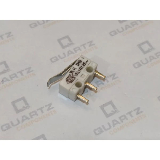
This document provides comprehensive technical specifications for the MV7 Series Subminiature MicroSwitches by Essen Deinki. It includes detailed information on electrical ratings, mechanical characteristics, dimensions, and application guidelines. Ideal for engineers and industry professionals seeking precise data on these high-performance micro switches designed for various industrial applications.
0 notes
Text
Central Locking Does Not Work: How to Make Repairs on Your Own?

Door device
The Passant driver's door is often a metal piece that is pressed against the body frame. Fastening is done with hinges and curtains. The door is equipped with closing mechanisms and consists of mechanical and automatic types. The most secure lock is the central lock. The filling of the web consists of:
window;
facing panel;
microswitch;
niche pockets;
door pillar;
outer and inner handles;
hinges, curtains;
limit switch;
castle;
plastic lining;
closer;
wiring.
According to the car service app the inner cavity is designed for the installation of speakers, power windows if the car was purchased as standard. When the door stops working, the reason may be hidden in any of the above mechanisms.
Lock
The issue with the locking mechanism is the most common one. To change this device, you are required to find out what exactly broke. Quite often, it is enough to replace the larva or lubricate the device. The lock contains a cylindrical shape with internal pins and teeth. When the key is rotated, the parts start to move: converge or diverge. In the case of a breakdown, the grooves are blocked and do not return to their original position.
End fittings
The door switch performs the features of a switch. Such fuel blows a transmit command to the car's power supply. It should be in working order, like other essential pieces of construction. The end mechanism is activated when the construction is opened/closed. The movement of the canvas is indicated by an illuminated light.
Disassembly of the trade winds, repair of the door limit switch will be needed in case of a solid frontal impact or wear of a spare part. There are two such devices in a single door. Wires internally connect them.
In the case of a rupture, the relay coil is de-energized, which can ultimately lead to a disconnection of the power supply to the loading electromagnet. To replace such a switch on the rear door, complete disassembly of the skin card is carried out.
Microswitches
Microswitches are directly related to the operability of the castle. These elements are related to the structural elements of the locking device. After the power supply has provided a lock signal, the pins are locked. Four types of microswitches are responsible for the operation of the front sheet: one closes, the other opens. The rest carry out the installation of the central lock. Signal sequence: block - power supply - acuator - lock.
Veils
The door is attached to the body by hinges. They are attached using special curtains and a locking bolt. Thanks to them, the door turns smoothly. Moreover, the repair of door curtains also requires replacing gaskets and screws. After revision, the movement will be very tight for several days. The best car repair app suggests that sagging of the door leaf indicates the need for replacing.
About the Company:
Are you looking for a trusted car repair shop that can provide you with all sorts of repair and maintenance services? At Getpitstop, we provide all sorts of repair services. Our car mechanics have many years of experience in servicing cars of various brands.
0 notes
Text
Zmin Driver Download

Minimum Impedance Zmin Ohms 7.98 7.5% €Moving Mass Mms g 13.7 Voice Coil Inductance Le mH 0.41 €Suspension Compliance Cms um/N 1058.3 Resonant Frequency Fs Hz 41.76 15% €Effective Cone diameter D cm 13.4 Mechanical Q Factor Qms 2.97 €Effective Piston Area Sd cm^2 141 Electrical Q Factor Qes 0.58 €Effective Volume Vas L 29.56. HPPSC1400SERIES22D9 device driver for Windows 7, XP, 10, 8, and 8.1. Stepper Drivers Obviously setting the correct stepper driver that is installed on the SKR V1.4 motherboard is important. While your particular stepper driver may differ, the below example is using TMC2208’s for UART mode, not standalone. Driver Specification Sheet Model No:: TC7FD00-04 Product Line: Tymphany Rev: 1 Last Update: 2017-04-25 21:32:09 Product Description This TC family 2.5 inch 4 ohm full-range driver,with ferrite magnet, paper cone and rubber surround, and steel basket, is designed to be a cost-effective high performance full range driver. Marlin is an optimized firmware for RepRap 3D printers based on the Arduino platform. Many commercial 3D printers come with Marlin installed. Check with your vendor if you need source code for your specific machine.
Zmin Driver Download Windows 7
Zmin Driver Download Windows 10
Zmin X1 Driver Download
Zmin Driver Download Pc
Endstops or limit switches are used on every moving axes of a 3D printer. The following chapter will provide information on:
Purpose of the endstop
Types of endstops
Configuring endstops and probes
Electromagnetic Interference / Electric Noise impact on endstops
Endstops fulfill two important functions in a 3D printer: Reference system for the axes system and safety.
Reference for the axes system
After powering up a 3D printer the printer’s controller board does not know at which position its axes are. Marlin indicates this by blinking question-marks in place of X, Y and Z on the LCD screen (v1.1.8 and older) or blinking ‘?’ in place of the coordinates besides X,Y and Z (Marlin v1.1.9 / v2.0.0 and newer).
This means the system needs first to establish its starting point of the physical (machine) coordinate system, a process called Homing. Homing can be initiated either via the G28 G-code or via the LCD controller.
Illustration 1: LCD indication not homed axes (Marlin <= v1.1.8)
Safety
The other important aspect of an endstop is protecting the hardware from damage. Should any movement try to exceed the physical limits of the machine, the endstop will cut the movement.
There are two main types of endstops. Hardware endstops and software endstops.
Hardware endstops
Hardware endstops are electrically connected to the endstop ports of the printer control board and will provide a signal when the endstop condition is met.
Illustration 2: Most common endstops (left to right): Micro switch, optical endstop (light barrier), hall sensor (magnetic)
Regardless of the type the basic way of working is the same:
A typically 5 Volt signal (High) drops to 0 Volt (Low): Normally closed (NC) switch
A 0 Volt signal (Low) rises to 5 Volts (High): Normally open (NO) switch
Since endstops are a safety feature NC switches are recommended as they will halt the machine should the switch be damaged, e.g. by a broken cable etc.
Probe as Z-Endstop
Probes can act like an endstop for the minimum Z-axis. While the typical endstop has a fixed position, the probe is mounted on the print-head and can freely move around the bed.
Illustration 3: Common probe types: Inductive (left), solenoid touch probe (right)
Some aspects of probe configuration are considered in this endstop introduction. Further reading is provided in the Chapter Probes Configuration, Auto Bed Leveling and Unified Bed Leveling.
Software Endstops
Typically 3D printers are only equipped with hardware endstops on one side of each axis (Minimum or Maximum of the respective axis). As discussed above this is used to determine the starting point (origin) of the machine coordinate system.
In order to also protect the other side of the axes software endstops should be defined in the firmware via the #define MAX_SOFTWARE_ENDSTOPS / #define MIN_SOFTWARE_ENDSTOPS directive. This then uses the value from #define (XYZ)_MAX_POS / #define (XYZ)_MIN_POS to determine the maximum distance between the physical endstop and the software commanded stop of the axis. Software endstops can be (de-)activated via the M211 G-code.
Background
By default, slicers generate G-code that places the base of a printed model at z=0 and build upwards from there. The result of homing the z-axis should thus place the build surface at the z=0 plane. After homing in z, the hardware z endstop is deactivated (unless you have set ENDSTOPS_ALWAYS_ON_DEFAULT in configuration_adv.h, which can be overridden by M120, M121), but to protect the hardware a software endstop is activated (which in turn can be overridden by M211 S0). This software endstop is located at Z_MIN_POS (defined in configuration.h) . This is normally at z=0 at the nominal location of the bed. Note that when using bed-leveling, this software endstop is applied to the uncorrected slicer generated z-values. This allows printing into the hollows of the bed, where z < 0.
We now describe some common Cartesian printer configurations, with and without bed-leveling probes.
Microswitch endstop - no bed leveling probe.
Here we mechanically adjust the bed and possibly additionally the microswitch trigger point to level the bed surface as close as we can to the z=Z_MIN_POS (normally = 0) plane. The z location of the hardware (microswitch) trigger point defaults to the value of Z_MIN_POS. It is possible however to use a microswitch trigger point above the bed by setting MANUAL_Z_HOME_POS to the z-coordinate of the trigger point. See here. Having the trigger point below the bed makes little sense as the nozzle would crash into the bed before the microswitch triggered on homing.
Probe used for homing and bed-leveling.
The probe should be mounted so that its trigger point lies below the extruder nozzle. Z_PROBE_OFFSET_FROM_EXTRUDER (negative!) is this vertical offset. This offset is applied by the firmware when homing in order to properly reference the coordinate system to the nozzle position. To measure this see here. For a mechanical probe like a BL-Touch, this offset is geometrically fixed. For a remote sensing probe (e. g. inductive or capacitive), the offset might vary with bed material. You can tweak it using M851.
Figure 1: Example configuration using BL-Touch for both homing and probing.
The process of bed-leveling generates an array of z-values of the bed heights at the probed points. Marlin interpolates these values to estimate the bed height at any given x/y location. Figure 1 illustrates the situation. While probing, all endstops are turned off so that the probe can reach into the valleys of the bed. To protect the machine in case of the probe failure during probing set Z_PROBE_LOW_POINT to limit the probing depth.
Microswitch used for homing, probe for bed leveling.
When homing, the printer is not protected against hardware endstop failure. This configuration uses a perhaps more reliable microswitch for homing, reserving the probe for bed leveling, where Z_PROBE_LOW_POINT provides failure protection. The configuration is illustrated in Fig. 2, requiring the use of both MANUAL_Z_HOME_POS and Z_PROBE_OFFSET_FROM_EXTRUDER Ideally, with an uneven bed, MANUAL_Z_HOME_POS should be adjusted so that z=0 lies halfway between the highest and lowest parts of the bed. This makes the maximum bed correction as small as possible.
Figure 2: Example configuration using a microswitch for homing, BL-Touch for bed-leveling probe.
Measuring offsets.
To measure an offset between a trigger point and the bed, lower the nozzle to the trigger point (by homing, if it’s the homing device), and note the z-value. Now turn off the software endstop temporarily (with M211 S0) to enable lowering the nozzle further down to the bed. Note the z again. The difference is the height of the respective trigger point above the bed.
Electromagnetic Interference (EMI) or electric noise, is an effect which can ruin the clean signal needed to properly and precisely measure electronically, be it temperature, endstop hits or any other value.
Sources and effect of EMI
In today’s life an abundance of sources for Electric Noise exists: Mobile phones, microwaves, WIFI, power supplies etc. In a 3D printer itself, there are also some prominent and strong sources of such noise:
Heated beds
Hot ends
Stepper motors
PWM modulation
The Electromagnetic Interference created by these sources are picked up by other components, either because they are directly connected or via radiation. The useful signal needed by the other components will be disturbed or even altered so much that it is no longer useful.
Effect on endstops / limit switches
In the following High = Logic 1 = 5 Volt will be used for a pressed switch and Low = Logic 0 = 0 Volt for a not triggered switch.
Ideal endstop characteristic
Illustration 4: Ideal Endstop
The above Illustration 4 shows an ideal endstop characteristic: Once pressed it jumps from Low to High and the printer control board realizes this in virtually no time.
Real endstop characteristic with low noise
Illustration 5: Real endstop characteristic
Illustration 5 shows:
There is no clean Low or High. Both states are somewhat unclean
Around the trigger point (marked in orange) an effect known as bouncing is shown: Due to mechanical influences the switch bounces between Low and High a few times before settling to High
Bouncing is unwanted but in case of endstops not a show stopper

Real endstop characteristic with peak noise
Illustration 6: Real endstop with EMI
This Illustration 6 shows:
Same characteristic as above but with a peak caused by EMI (marked in red)
The peak is high enough to be falsely detected by the printer control board as pressed switch, potentially ruining a running print
Countermeasures
There are numerous counter measures preventing noise:
Shielded cables / twisted cable pairs
Cable routing (route signal cables away from power cables)
Software filtering
Hardware filtering
In the following the options 3 and 4 will be discussed further.
Software filtering
Beginning with Marlin v1.1.9 and v2.0 the software measures against endstop noise are improved and exposed as a setting. Prior versions already implemented filtering that is permanently active. For the sake of precision, this now has been exposed as a user setting in Configuration.h and deactivated by default.
Activating this option will lead to following endstop characteristics:
Illustration 7: Endstop with software filtering
The yellow marked area in Illustration 7 shows the area where the software compensation is active. The first yellow area is an effect due to noise and the algorithm decides that no endstop is triggered since the signal falls back to a Low state.
The second yellow area marks the spot where a real and wanted endstop triggering has happened. Now the algorithm basically “watches” the situation for some milliseconds until deciding if the endstop really is triggered or if an EMI / Noise effect needs to be compensated. This will lead to delays and finally to a precision loss in the detection of the endstop.
Depending on the printer’s geometry and affected endstop, this precision loss may result in issues especially concerning the bed leveling. Using this feature is not recommended. Implementing some type of hardware filtering is strongly preferred.
Hardware Filtering
Hardware filtering can range from a simple capacitor in parallel to the switch over a resistor / capacitor combination (RC-unit) up to opto-couplers and flip-flops.
Board
Some printer controller boards already contain such filters located at the endstop connectors. Unfortunately the popular RAMPS v1.4 design does not. A deficit that has been corrected with the RAMPS v1.4.2 design:
Illustration 8: RAMPS v1.4 vs v1.4.2
Endstop PCB
For 3D printing ready made filtered endstops are available, e.g. according to the Makerbot design:
Illustration 9: Endstop PCB with RC unit
Endstop with capacitor
A more simple variant, that can easily be fitted to existing endstops is a 100nF capacitor, soldered over the two endstop connector pins (in parallel):
Illustration 10: Endstop with 100nF capacitor
Effect of the hardware filtering
Illustration 11 below shows the effect of such hardware filtering: The noise level is smoothed and peaks will be reduced so much that they no longer will cause false readings. Additionally the fast bouncing at the beginning of the triggering will also be damped.
Illustration 11: Endstop characteristic with hardware filter
Conclusion
Zmin Driver Download Windows 7
Electrical Noise should not be underestimated. It is invisible but it may lead to strange effects that are very hard to diagnose due to its spurious nature. Simple measures like adding a capacitor will already improve the situation considerably, overall improving reliability of the machine.
6Connection Method
MKS BaseV1.2 3D Printer Controller Board (RAMPS 1.4 + Arduino 2560 remix board)

Intruduction
The new MKS Base 1.2 3D Printer Controller board combines and improves the assets of the RAMPS 1.4 and Arduino Mega 2560 boards on a fantastic single board solution. The MKS Base 1.2 is an optimal 3D printer controller solution for your Reprap 3D Printer.
Main features
Zmin Driver Download Windows 10
The MKS Base 1.2 solves interface connection problems between the Arduino Mega 2560 and RAMPS 1.4 boards by having both integrated into a single board
5 Stepper Motor Driver Slots. The boards supports a wide variety of Stepper Motor Drivers - most notably A4988, DRV8825 and Ice-Blue Stepper Motor drivers drive
The MKS Base 1.2 board uses a high quality 4-layer PCB which optimizes heat dissipation
Firmware can use the same configuration as RAMPS 1.4
Easy DISPLAY + SD-CARD connector - compatible pin header on board for 12864 & 2004 LCD Display controller panels.
6x end stop connectors with power supply Xmin/Xmax/Ymin/Ymax/Zmin/Zmax
3 x 5V output, 3 x Power voltage output
Reserve motor pulse and direction output port
Support 12V-24V power input
List

MKS BaseV1.2 3D Printer Controller Board
usb cable
Connection Method
A. Mount DRV8825 correctly, don’t mount reversely, or they will be burnt, as shown below:
Zmin X1 Driver Download
B. As for 2004LCD, connect ESP1 to ESP1, ESP2 to ESP2, as shown below:
C. Diagram connection as shown below:
Connection Method
Install Diver Software
A. Connect the main board with computer, and then right click “Computer” to enter “Device Manage”. B. Double click “Other devices”, appearing “USB Serial Port”. Then, right click “USB Serial Port” and select “Update Driver Software” to install driver software. After that, select “Browse my computer for driver software” to find the file. Browse to search for driver software. After your driver software updated, click “Close” to finish.
C. Finally, installation is done, and double click “Ports”in “Device Manager”, you can see “USB Serial Port”.
Install development environment software IDE
Double click arduino-1.5.6-r2-windows to start.Select “I Agree”to accept license agreement. Select components to install and click “Next”. Click “Browse” and select another folder. Click “Install” to start the installation. Finally, wait for a few minutes to finish.
Install Firmware for Main Board

A. You must close Arduino IDE firstly, and then place three libraries LiquidCrystal, SPI and U8glib from Marlin_Marlin_v1→ArduinoAddons→Arduino_1.x.x→libraries into Arduino/libraries. B. Enter Marlin_Marlin_RAMPS_2004_Ver1 this folder, double click Marlin_Marlin_RAMPS_2004_Ver1.ino this file, finally click “Tools” to set “Board”and “Port”. After verifying, write code. Done uploading.
C. After upload the firmware the LCD will display some parameter as shown below:
Zmin Driver Download Pc
Install Slicer Software Repetier-Host
First, run this application
Click “Next” to continue.
Check “I accept the agreement”, and click “Next” to continue. Select destination location, and click “Next” to continue. Check components that should be installed, and click “Next” to continue.
Select star menu folder, and click “Next” to continue. Click “Next” to continue. Click “Install” to install. Click “Finish” to exit Setup.
Application of Slicer Software
A. Run Repiter-Host,click Load to open a printing model.
B. Click Printer Settings to complete some setup, referring to below figure.
C. Enter Object Placement to set placing position, printing size and so on.
D. Click Slicer to set slicer, like printing speed. After setting slicer, click Start Slicing to begin slicing.
E. After slicing, go to Preview→G-Code Editor, copy G-Code to SD card, and then insert the card into the main board. It is time to kick off the print! Though the LCD screen go to : Print from SD→Desired File. Or you can connect your 3D printer to computer using a USB cable to start the print.
F. Click “Connect”and then click “Start Print” to begin the print. After some time, your printer gets ready and the buzzer rings, then you should press the button on LCD to start.
G. We just introduce a simple method about printing. Thanks to selling only main board by us, you should design your own structure and outlook of your 3D printer, and you should also set your own configuration to meet your need. After you assembling your printer, the printer need to be leveled, so you can make some setup in Preview and Manual Control, and surf the internet for further information.
H. We have a G-Code to test the main board. Power it on, open limit switch and stepper motor, drive three motors; put a Fnbduino.gco file to Preview, click Start Print, if the motors rotate, X/Y/Z value in Manual Control changes, the main board works as shown below:
Resources
Repetier-Host Download https://www.repetier.com/download-now/
Arduino IDE Download https://www.arduino.cc/en/software
Firmware, Driver Software, Testing G-Code and Mask Printing Model Download https://fs.keyestudio.com/KS0089
Buy from

Official Website
Retrieved from 'http://wiki.keyestudio.com/index.php?title=Ks0089_MKS_BaseV1.2_3D_Printer_Controller_Board_(RAMPS_1.4_%2B_Arduino_2560_Remix_Board)&oldid=30618'
0 notes
Text
Switch
https://www.viyorktech.com/products/switch.html
A switch is an electronic device that turns on or off the circuit or causes it to flow to another circuit. The most common switch is a human-operated electromechanical device that has one or more electronic contacts.
The "closed" of the contact means that the electronic contact is switched on and allows current to flow; The "open" of a switch means that the electronic contact is open and does not allow current to flow.
There are several types:
1. According to the using classification: Wave switch, band switch, recording switch, power switch, pre-selected switch, limit switch, control switch, transfer switch, isolation switch, travel switch, wall switch, intelligent fire switch, etc.
2. According to the structure classification: Microswitch, boat switch, toggle switch, toggle switch, button switch, button switch, and fashion film switch, point switch.
3. According to the contact type classification: Type A contact, type B contact and type C contact.
4. According to the switch classification: Single control switch, double control switch, multi-control switch, dimmer switch, speed regulating switch, splash box, doorbell switch, induction switch, touch switch, remote control switch, intelligent switch, card plug and take electricity switch, special switch for Bath ba.

0 notes
Text
Bump Switch - SPST Snap Action with Lever (Micro Switch)
This is a SPDT Snap Action Micro Switch with a lever for actuating the snap action and the switch to work. It has three pins/legs, namely Common (C), Normally Closed (NC), and Normally Open (NO). This is SPDT Single Pole Double Throw switch and can be used as both NO Normally Opened Switch or NC Normally Closed Switch separately or simultaneously, depending on the application. The lever is used to press a tiny momentary push-button below it which will establish contact between Common (C) and NO terminals. The switches can be used to create bump sensors for robots or as limit switches in electronic appliances like microwaves, printers, Refrigerators, and Hospital Beds. It can also be used to determine the state of operation like whether the appliance is working or not.
SPECIFICATIONS
Microswitch Actuator: Lever
Contact Configuration: SPDT
Switch Terminals: Solder
Contact Voltage AC: 250VAC
Contact Current Max: 10.1A
Operating Force: Max 1.47N
Buy this Bump Switch: https://quartzcomponents.com/products/bump-switch-spst-snap-action-with-lever
0 notes
Text
Benefits of a Micro Switch?
Microswitches work by responding immediately to a weight change or a physical change. This activity is named as the snap activity. It is most ordinarily utilized in the gadgets, clinical, and car ventures. These switches are planned and displayed in different manners, contingent upon their job. It accompanies distinctive actuator styles and exchanging setups. Microswitches are made of different materials. They can be made of phenolic plastic or polyester.
The microswitch has an actuator which, when pushed, triggers the snap activity inside the microswitch. At the point when the weight is eliminated, the actuator lets the change to re-visitation of its unique position. It is additionally upheld by a spring that applies a push from within the switch. The microswitch has a spring structure with a roller that triggers it. The snap movement is set off when there is a little physical weight, which is increased.
At the point when the snap action occurs inside the microswitch, you can hear the snap sound. The fundamental arrangement of a microswitch isn't uncommonly puzzled. It goes after the reason of brief action on account of a physical change or weight. These limits are fundamental to work flawlessly with no slip-up.
Employments of Micro Switches:
As referenced before, miniature switches are utilized in fluctuated frames and shifted places. These are utilized in weighty modern advancements and can be found in our regular daily existence as well. These are a portion of the normal employments:
Utilized in security mechanical assembly
Utilized in microwaves and their entryway interlocks
Likewise utilized in printers to distinguish any paper jam
It identifies jam in candy machines and furthermore to detect the coin when it enters the machine.
Utilized in charge boards and apparatuses like solenoids, lights, little engines, and the sky is the limit from there.
Additionally utilized in different sorts of entryway instruments to detect the opening and shutting.
Utilized as control switches, limit switches and furthermore utilized as time instruments
Preferences:
Microswitches are the most solid switches in the market. They work precisely and over and again without bringing about any disappointment. They likewise come in different structures that fit the different requests of the switches. It arrives in an assortment of materials and exchanging positions. These switches are the most trusted and the most sturdy switches, and subsequently these are the most needed with regards to wellbeing related items. These switches are reasonable and can be purchased in mass without any problem. Indeed, even the ease switches work for quite a while as a general rule.
All the advantages make these switches so significant and needed in the market. These come at truly reasonable costs in any event, when purchased in mass. Our organization gives the best arrangements and the best quality miniature switches. These switches are dependable, solid, and minimal effort, making them the most alluring alternative.
On the off chance that you are hoping to purchase such miniature switches that you can depend on, visit . for more data. Our switches consistently surpass consumer loyalty and give the most secure and tried switches. Get in touch with us on the off chance that you are searching for a miniature change maker to purchase these switches in mass at entirely moderate costs. We pay attention to the security work very and give the most dependable miniature switches that play out 1,000,000 rounds no matter what.
0 notes
Text
Sparkfun’s Spectacle - Playing with the Lights

For those that missed Yesterday’s post, Sparkfun (www.sparkfun.com) sent me their new Spectacle (https://www.sparkfun.com/pages/spectacle) kit to play with. Spectacle is made for people who don’t want to get into electronics as a hobby but want to add lights, sound or motion to their projects. Rather than deal with soldering and code you plug the boards together and program with their web app. You can check out the app here: https://spectacle.sparkfun.com/
Today I am looking at their lighting kit: https://www.sparkfun.com/products/14170?_ga=2.215536722.43721405.1496880363-1862285132.1496769715 The pre-set rainbow effect:

What it Comes With:
1x Spectacle Director Board The director board is the main board. You plug this into a power source (either wired to a wall or a battery pack) to power most projects. You can also connect your phone or computer into the director board with an audio cable. This allows you to upload your programming.
1x Spectacle Light Board This is a board with 4 slots for the LED strip to be plugged into. The slots are labled and you reference those slots when doing the programming.
1x Spectacle Button Board This is board comes with 8 slots for buttons to be added in (numbered 0-7) and a small button on the board (number 8) which can be used as-is.
1x Addressable LED RGB Strip — 1m This was a long strip of LEDs that can display RGB colours. Mine came with 60 LED pixels. This hooks into the light board via a connecting wire but you can also hook other LED strips together for a longer strand.
1x White Concave Button This hooks into the button board so you can click it and make things happen.
2x Female Spade Connector Wire — 3ft These allow you to hook the button up to the button board.
1x JST to JST-SM Wire — 1ft This is used to connect the LED RGB Strip to the light board.
3x Audio Cable TRRS — 3ft The audio cables are used to connect the boards together or connect your phone/computer to the director board. They just slide in the audio ports for easy connectivity.
1x USB micro-B Cable — 6ft
1x USB Wall Charger — 5V, 1A
2x USB Lithium Ion Battery Pack — 2.2Ah The wall charger or the battery pack can be plugged into the director board to power your device. An additional battery pack can be plugged into the light board if more power is needed.
My Set Up:
I tried this out with two different set-ups.
1) Wall Plug > Director Board > Button Board > Lightboard with LED Strip
This was set up so when you pushed button #8 (a button on the board) the light would turn on.
2) Battery Pack > Director Board > Light Board with LED Strip
This was set up so that at set intervals the lights would turn on.

Lighting Options:
There are a lot of pre-set options for special effects: Rainbow Effect, Theater Chase, Scanning Effect, Twinkle Effect, Lightning Effect, Flame Effect and Fade Lights. There were also two options to fill specific pixels: fill and pixel.
The flame effect with a red colour applied:

Working With It:
Good
Really like how easy it is to set up. Everything clips together well.
Once you had one effect working, it was easy to switch out that effect
You are able to set up the effect to work with a button or just activate on its own, which makes it useful for different projects
The light-strip is flexible and the LEDs are very bright!
Bad
Google Chrome blocks the spectacle app (Privacy Error), so you will need another browser on your computer or mobile device to program.
When something goes wrong, there is no error code or obvious error flags. For a beginner device, you need to do a lot of playing around and testing to find out where the problem is. However they do have a troubleshooting FAQ. I would like to see a troubleshooting sheet shipped with the product to help with identifying issues or something in their app to help you troubleshoot.
Notes
Your volume must be all the way up to transmit the information and not all phones can transmit at a high enough volume to effectively transfer data. You may need to use a computer or alternate device if your phone has this issue.
Some battery packs will turn off if not enough energy is being pulled from them. You will not want to use these packs to power your projects.
The twinkle effect:

For Cosplay:
The LED strip is really great for where you need a strip of lights. It would go well in a sword, gun or other prop and may work well to light up a visor or pieces of armor. This Lightsaber is a good example of the lights being used. Where it wouldn’t work as well is in something like Shiny Chariot’s wand where the lights are more spaced out and are somewhat non-linear. It also would have trouble with something rounded like Iron Man/Tony Stark’s arc reactor, where the lights should all be forward facing. I would love to see them expand on their options.
Because you aren’t doing your own wiring, there may be more bulk than if you were cutting and soldering your own wire. This is going to work well in projects that allow you to hide the wiring and battery packs.
Since this runs on a battery pack you will eventually need to re-charge the pack. You will want to keep this in mind when using Spectacle in your project as you will either need to remove the pack or have a way to access the charging port.
In instances where a button is used, the existing concave button is really large and would be hard to hide in most props (but would be awesome for an arcade sona cosplay). However you can take off the concave button and be left with a microswitch which is much easier to work with. While the button board also has a button on it, I think it would be difficult to position the board so that button is accessible.
The programming is a little limited. I think it would be difficult to do something like a Daft Punk helmet, at least at this time. I hope they expand their electronic and programming options to allow for some slightly more complex builds to benefit from the ease of putting together this kit.
—Duckie / Admin
286 notes
·
View notes